T
tonyhoang195
 [TẶNG BẠN] TRỌN BỘ Bí kíp học tốt 08 môn
 Chắc suất Đại học top - Giữ chỗ ngay!!
ĐĂNG BÀI NGAY để cùng trao đổi với các thành viên siêu nhiệt tình & dễ thương trên diễn đàn.
First of all I want to say many thanks to Reaprevenge for finding back this tutorial that was lost during the PST crash.
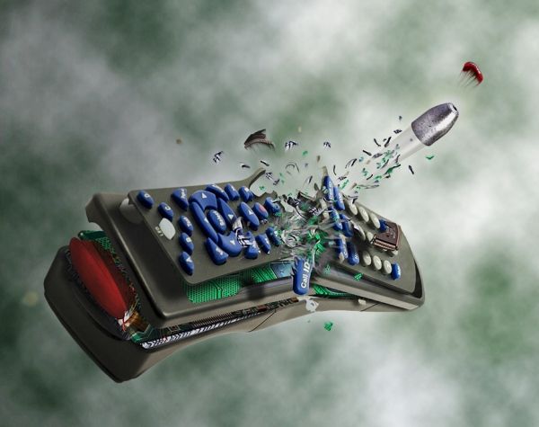
In this tutorial I'm going to show you how to make a nice bullet shot effect. I decided to use a technological object such as a remote control to show a lot of tiny parts flying off after the impact: the circuit board, the buttons, a few chips...
For this tutorial I used Photoshop CS3 and I think is pretty necessary. It also recommended that you still know how to:
- select an area with the pen tool
- how the liquify filter works (we're not going to use it much but it can be useful for some threatments).
I used these sources:
http://www.adigitaldreamer.com/gallery/displayimage.php?album=6&pos=15
http://www.adigitaldreamer.com/gallery/displayimage.php?album=6&pos=9
http://www.adigitaldreamer.com/gallery/displayimage.php?album=6&pos=10
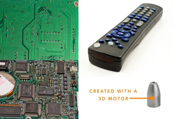
The bullet used in this tutorial is designed by me with Solidworks 3D Pro but you can find easily a free stock photo of a bullet. And if you don't find it you can use mine, there's no problem.
Ok let's begin!!
End result:
Step 1
Ok here are the sources.
Step 2
Before beginning to work on our sources let's see this process which is going to be fundamental for our work.
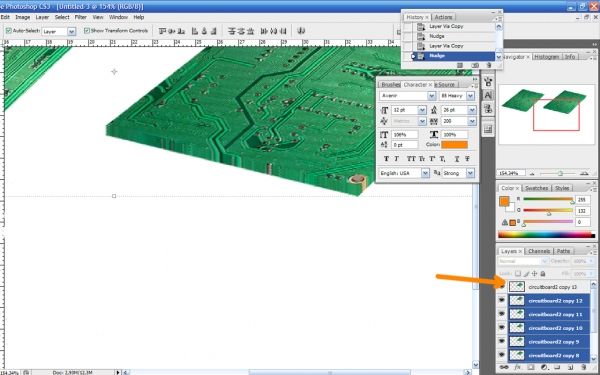
The process is: how to make a 3D effect. Let's suppose that we have this layer with a circuitboard and we want to make it tridimensional to get rid of this "flat" effect.
Follow the istructions and keep them clear in your mind.
1 Duplicate the motherboard layer (Ctrl+J)
2 press the "up" key on the keyboard
3 Do this a few times (depends on the situaztion may be 2-3 mauy be 8-9 or more...)
4 merge all the layers preserving th one on top (view the image below)
5 blur the merged layers with a Gaussian blur ->amount=1
6 Burn a little th merged layers
7 Blur a little the edges of the layer on top
8 merge all the layers
Done! It's not 2D anymore
Step 3
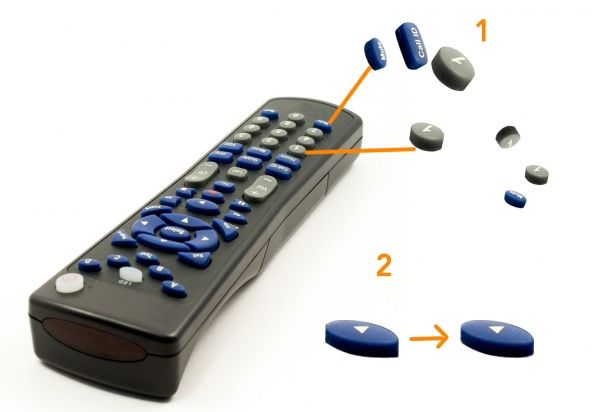
Now let's begin to select some buttons: to make a clean rounded selection use the pen tool and design your path, then right click and "make selection" (feather to zero).
After that, copy your selection in a new layer (so Ctrl+C and Ctrl+V )then work with "liquify" (filter->liquify) to make them rounded and to extend the missing parts (1).
If you want to jump this part (1) well be clever and select directly a button which is still ready to be used! As I did in (2). Some cleaning is anyway necessary in both situations, so use carefully the eraser tool.
Step 4
Let's hide those buttons they can be useful later, but we still don't know it.
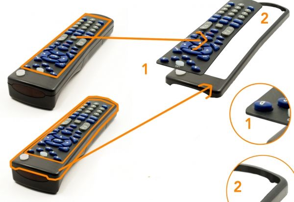
Now create the first two parts: select with the pen tool the buttons' surface (1) (I hope you get what I mean) and then copy and paste.
Do the same with the part of the box below (2).
Now to create the 3D effect on the first part is really easy (look at step 2 of this tutorial) but on part (2) is not so easy. Let's see it in next step
Step 5
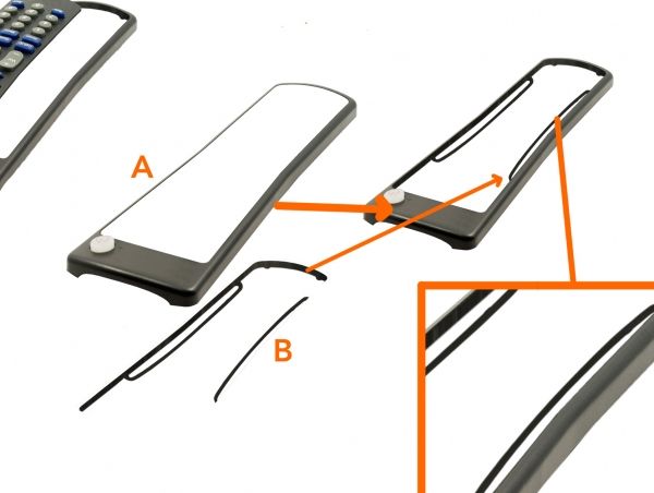
Ok we have our selection just made (A) in the previous step, so let's draw the 3D part on a new layer below the (A).
Use a brush and if you want a pen tool can be useful (is up to you and your skills) I drawed these "wings" because it's supposed that the surface with buttons is linked to something...well I really don't know I never opened a remote control =)
Step 6
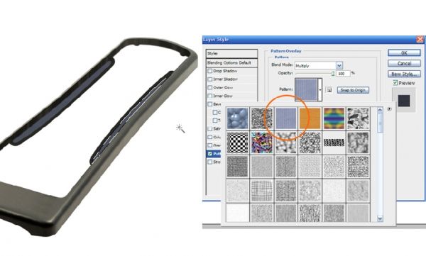
I decided to fill these lttle wings with a pattern.
Create a new layer below this shape, select with the magic wand tool (W) the two blanck parts, then go to edit-> fill (choose a 50% grey).
Go to blending options and set pattern overlay. Choose the pattern in the image and set his blending option to multiply.
Click ok, select the three layers and link them (or merge them if you're really really sure)
Step 7
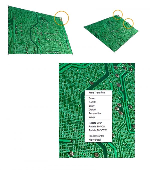
Ok well done. Now take the circuitboard source and let's make it realistic...as it really fits in the remote control. To do it in perspective you can use the "vanishing point" (filter -> vanishing point) or do it manually with the Edit->Transform->free transform. I recommend you the last one because it's easier for this work and you have an istant feedback of what you're doing. For example here I show how you can distort it: just pressing the Ctrl + click and drag on one of the litle squares around the image you're able to distort and....free transform!!
Step 8
Ok after the previous little lesson about the free transfom let's work seriously on our circuitboard.
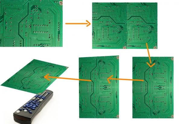
Duplicate it with Ctrl+J, make the two layers aligned each other, then make the desired perspective using the other layer with the buttons as a reference.
Step 9
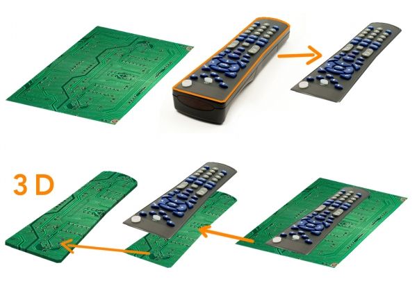
Ok now our motherboard is in theright perspective but it doesn't have the right shape: to make it match with the "buttons' layer" move it on top then Ctrl+click on the layer's thumbnail (the layer with the buttons) then Ctrl+Shift+I to select inverse and finally click on the motherboard layer's and press Canc.
Give it a volume then.
Step 10
Ok now let's create from zero a chip that will be inserted in our circuitboard. Create a shape layer: use a "rounded rectangle tool" and fill it with a random colour. then go to blnding options and apply these settings.

(Continues)
In this tutorial I'm going to show you how to make a nice bullet shot effect. I decided to use a technological object such as a remote control to show a lot of tiny parts flying off after the impact: the circuit board, the buttons, a few chips...
For this tutorial I used Photoshop CS3 and I think is pretty necessary. It also recommended that you still know how to:
- select an area with the pen tool
- how the liquify filter works (we're not going to use it much but it can be useful for some threatments).
I used these sources:
http://www.adigitaldreamer.com/gallery/displayimage.php?album=6&pos=15
http://www.adigitaldreamer.com/gallery/displayimage.php?album=6&pos=9
http://www.adigitaldreamer.com/gallery/displayimage.php?album=6&pos=10
The bullet used in this tutorial is designed by me with Solidworks 3D Pro but you can find easily a free stock photo of a bullet. And if you don't find it you can use mine, there's no problem.
Ok let's begin!!
End result:

Step 1
Ok here are the sources.

Step 2
Before beginning to work on our sources let's see this process which is going to be fundamental for our work.
The process is: how to make a 3D effect. Let's suppose that we have this layer with a circuitboard and we want to make it tridimensional to get rid of this "flat" effect.
Follow the istructions and keep them clear in your mind.
1 Duplicate the motherboard layer (Ctrl+J)
2 press the "up" key on the keyboard
3 Do this a few times (depends on the situaztion may be 2-3 mauy be 8-9 or more...)
4 merge all the layers preserving th one on top (view the image below)
5 blur the merged layers with a Gaussian blur ->amount=1
6 Burn a little th merged layers
7 Blur a little the edges of the layer on top
8 merge all the layers
Done! It's not 2D anymore

Step 3
Now let's begin to select some buttons: to make a clean rounded selection use the pen tool and design your path, then right click and "make selection" (feather to zero).
After that, copy your selection in a new layer (so Ctrl+C and Ctrl+V )then work with "liquify" (filter->liquify) to make them rounded and to extend the missing parts (1).
If you want to jump this part (1) well be clever and select directly a button which is still ready to be used! As I did in (2). Some cleaning is anyway necessary in both situations, so use carefully the eraser tool.

Step 4
Let's hide those buttons they can be useful later, but we still don't know it.
Now create the first two parts: select with the pen tool the buttons' surface (1) (I hope you get what I mean) and then copy and paste.
Do the same with the part of the box below (2).
Now to create the 3D effect on the first part is really easy (look at step 2 of this tutorial) but on part (2) is not so easy. Let's see it in next step

Step 5
Ok we have our selection just made (A) in the previous step, so let's draw the 3D part on a new layer below the (A).
Use a brush and if you want a pen tool can be useful (is up to you and your skills) I drawed these "wings" because it's supposed that the surface with buttons is linked to something...well I really don't know I never opened a remote control =)

Step 6
I decided to fill these lttle wings with a pattern.
Create a new layer below this shape, select with the magic wand tool (W) the two blanck parts, then go to edit-> fill (choose a 50% grey).
Go to blending options and set pattern overlay. Choose the pattern in the image and set his blending option to multiply.
Click ok, select the three layers and link them (or merge them if you're really really sure)

Step 7
Ok well done. Now take the circuitboard source and let's make it realistic...as it really fits in the remote control. To do it in perspective you can use the "vanishing point" (filter -> vanishing point) or do it manually with the Edit->Transform->free transform. I recommend you the last one because it's easier for this work and you have an istant feedback of what you're doing. For example here I show how you can distort it: just pressing the Ctrl + click and drag on one of the litle squares around the image you're able to distort and....free transform!!

Step 8
Ok after the previous little lesson about the free transfom let's work seriously on our circuitboard.
Duplicate it with Ctrl+J, make the two layers aligned each other, then make the desired perspective using the other layer with the buttons as a reference.

Step 9
Ok now our motherboard is in theright perspective but it doesn't have the right shape: to make it match with the "buttons' layer" move it on top then Ctrl+click on the layer's thumbnail (the layer with the buttons) then Ctrl+Shift+I to select inverse and finally click on the motherboard layer's and press Canc.
Give it a volume then.

Step 10
Ok now let's create from zero a chip that will be inserted in our circuitboard. Create a shape layer: use a "rounded rectangle tool" and fill it with a random colour. then go to blnding options and apply these settings.

(Continues)
Last edited by a moderator:
